
Umbrella Check Valves for Efficient Fluid Control
Product Number: V015612800
Umbrella valves are single-component, in-line, one-way check valves that function effectively when paired with a flat seat. These valves are normally closed and are ideal for applications requiring a precisely defined low opening pressure. They offer excellent resistance to backflow leakage. By combining the valve with an appropriately designed seat, the balance between forward flow and reverse pressure resistance can be optimized.
Materials of Construction
- Part Number: V015612800
- Product Group: Umbrella
- Material Number: VL1502T118
- Material Type: Fluoroelastomer (FKM)
- Material Color: Black
- Durometer: 58
Design Characteristics
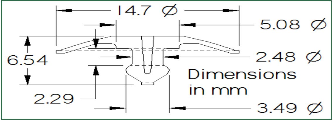
- OD: .580in, 14.73mm
- Cracking Pressure: Push
Working Principle
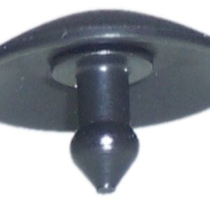
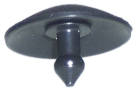
Umbrella valves consists of a dome shaped elastic valve body which provides a sealing function in the backflow direction when mounted in a seat. Opening pressure is determined by the amount preload applied to the valve body and by the skirt design. Forward flow is a function of pressure differential over the flow path cross sections and the skirt design.
Mounting Instructions
Umbrella valves can be mounted in any orientation, providing versatility in application. Installation is straightforward, with this design featuring a push-in mounting method. Pull-in and other mounting options are also available. The vented stem in this design eliminates the need for a separate vent hole. To ensure proper functionality, the umbrella valve’s outer diameter (OD) should have sufficient clearance within the housing assembly to avoid restricting flow.
Photo/Rendering
Technical Drawing
Performance Characteristics
Opening Pressure
Diagram
Definition
Opening Pressure is the differential pressure required for the valve to allow forward flow that meets the specified flow threshold. As the flow threshold increases, the Opening Pressure will also increase. Conversely, reducing the flow threshold will result in a lower Opening Pressure. Water test data is available upon request.
Reverse Leakage
Diagram
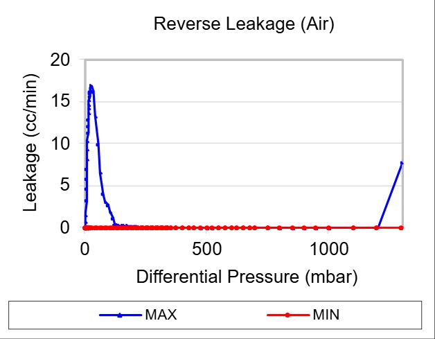
Definition
Leakage, or reverse flow, is measured by gradually increasing the backpressure across the valve, starting from zero. Please note that the leakage graph uses a different scale compared to the flow graphs. Water test data is available upon request.
Forward Flow
Diagram
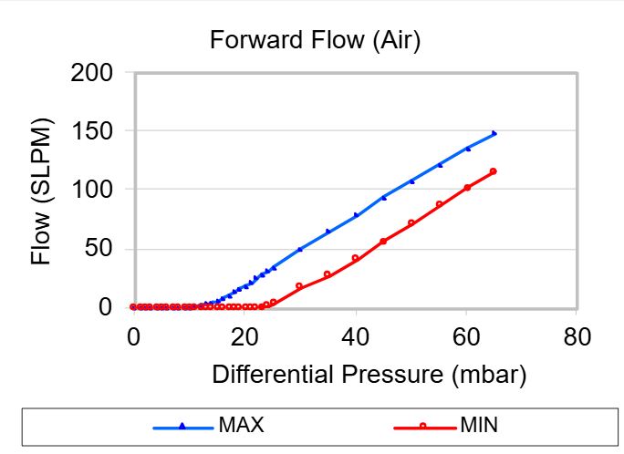
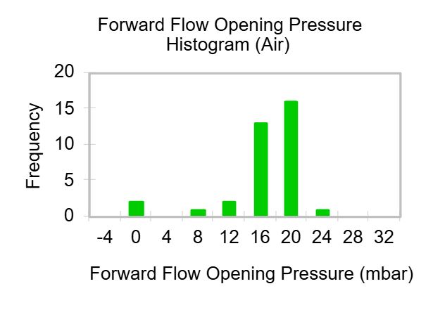
Definition
Flow and differential pressure are measured simultaneously as the inlet pressure increases from zero. Once the maximum flow is reached, the pressure is gradually reduced back to zero, with flow and differential pressure measured throughout the process. The chart displays the minimum and maximum flow values recorded during tests of multiple samples at each pressure level. Water test data is available upon request.
Vernay Quality Policy
Vernay is committed to the highest level of quality and service to our customers. We focus on innovation and continuous improvement in all areas of our business and accomplish these goals through our quality management system. Maintain our existing quality certifications (ISO/IATF-16949, ISO 9001, and ISO 13485).