
Bi-directional Check Valve
Product Number: V133610200
Bi-directional valves can be used where it is desired to open for flow at different pressures in each direction. They are also commonly used as catheter-type seals where it is desired to insert around a shaft.
Materials of Construction
- Part Number: V133610200
- Product Group: Bi-Di
- Material Number: VL601M119
- Material Type: Polyisoprene
- Material Color: Grey
Design Characteristics
Function
VA3768 is designed as a general purpose vent valve or for use with catheters in the range from 2.2 to 2.9 mm in diameter.
Working Principle
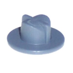
The cylindrical shaped dome has a slit through the rubber. Due to the dome shape a higher pressure is needed when applied to the outside of the dome (reverse flow) than the inside to open the valve (forward flow). When used as a catheter-type seal the slit seals around the shaft when it is inserted from the inside and then typically the opening pressure from the outside is high enough to prevent flow when the shaft is removed.
Mounting Instructions
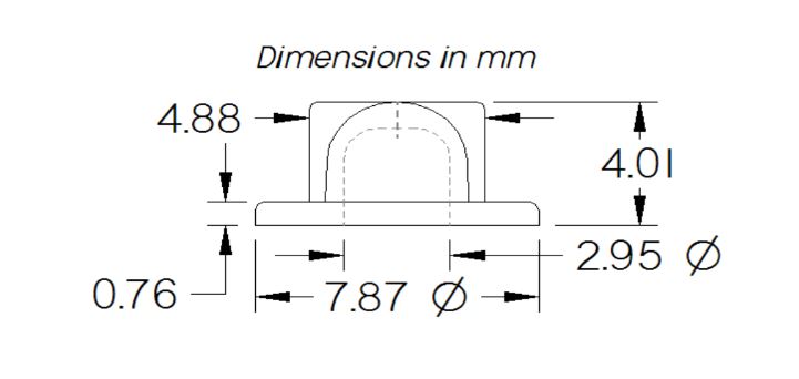
Bi-directional valves are mounted by squeezing the flange about 15% of thickness. The flutes (4.88 mm dimension) are normally not compressed in the bore but can be compressed gently if desired to increase the opening pressure.
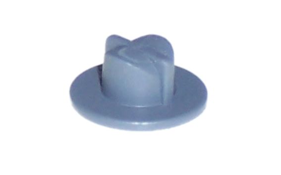
Photo/Rendering
Technical Drawing
Performance Characteristics
Opening Pressure
Diagram
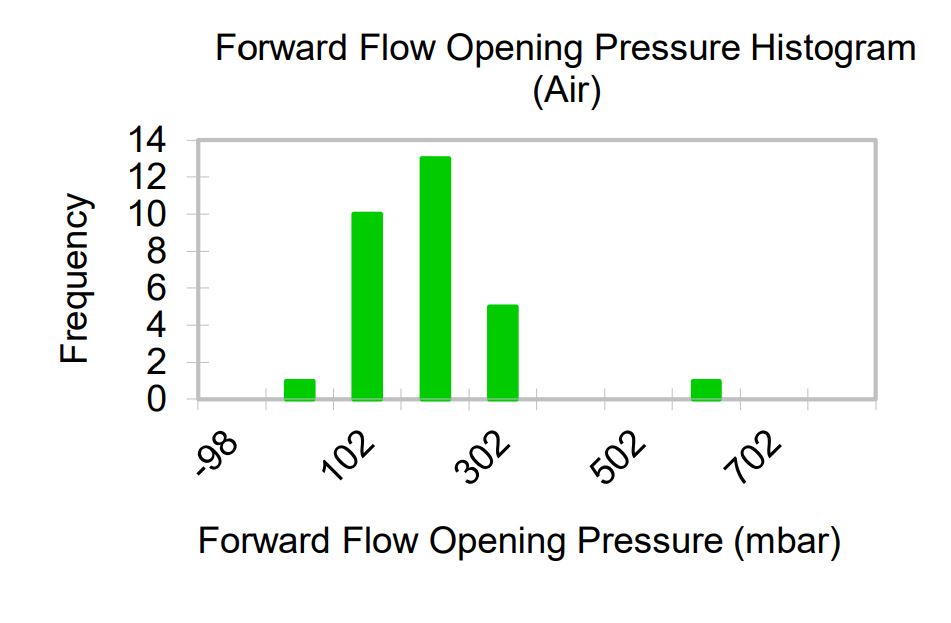
Definition
Opening Pressure is defined as the differential pressure at which the forward flow through the valve reaches the flow threshold. Opening Pressure will increase as the flow threshold is increased, and will decrease as the threshold is decreased.
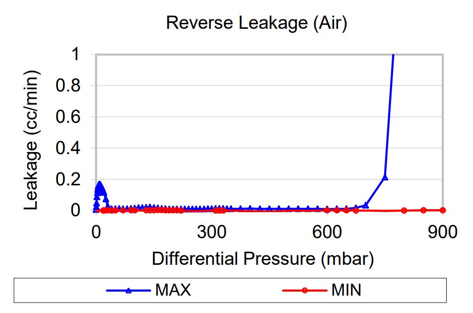
Reverse Leakage
Diagram
Definition
Leakage, or flow in the reverse direction, is measured while increasing the backpressure across the valve, starting from zero. Please note that leakage graph is on a different scale from those of flow.
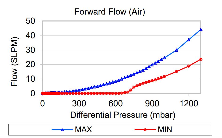
Forward Flow
Diagram
Definition
Flow and differential pressure are measured simultaneously while increasing the inlet pressure, starting from zero. After reaching a maximum flow, the pressure is reduced to zero while measuring flow and differential pressure. The chart shows the minimum and maximum flows measured during the tests of multiple samples at each pressure.
Vernay Quality Policy
Vernay is committed to the highest level of quality and service to our customers. We focus on innovation and continuous improvement in all areas of our business and accomplish these goals through our quality management system. Maintain our existing quality certifications (ISO/IATF-16949, ISO 9001, and ISO 13485).